The running lights/navigation strobe circuit
Apart from lit windows, the most basic lighting you’ll see on a starship model (I’m mostly talking the world of Star Trek) will be running lights and navigation strobes. Running lights are the red and green lights that indicate port and starboard respectively and blink at a slow, even rate, about one second on and one second off. Judging from the video below, and assuming 24 frames a second, that’s seems about right.
Navigation strobes (or collision strobes) flash very quickly and are off for a comparatively long time. The video shows the light on for just one frame and off for about a second. All my calculations are off if the video was converted to 30 fps, of course. The original Enterprise, no bloody A, B, C, D or even refit, did not have strobes.
Running lights are relatively easy to reproduce using the basic 555 timer circuit, but strobes take a little more ingenuity because strobe are more off than on. And by using the dual 556 timer, you can use one chip to power both lights and strobes. Before we get into the technical details, however, allow me to introduce the 555.
The 555 astable circuit
 According to the wikipedia article, the eight-legged NE555 chip has been around since 1971 and has three operating modes, but the one we’re interested in is the astable mode, which is just a fancy way of saying a continuous on/off pulse (a square wave), that when hooked up to an LED produces a blinking light. It requires three components connected to the chip to operate: two resistors and a capacitor. Additionally, three legs, or pins, are connected by jumpers. Seven of the eight pins are connected to something; only the control pin is unused.
I don’t pretend to understand exactly how the circuit works, but basically the capacitor builds up a charge, and the rate at which the charge accumulates is controlled by resistor 1 for the high (on) state and resistor 2 for the low state. The 555 chip measures how long it takes for the capacitor to reach about 2/3 full (watch the video below for why 2/3) before changing from high to low state. The video below is a wonderful explanation of how the 555 chip works.
Trying to get the timing/frequency you want for your running lights then requires determining the values you want for R1, R2 and C1, that is, resistor 1, resistor 2 and the single capacitor in the circuit. The higher the rating of the capacitor, usually measured in microfarads (µF) for our purposes, the longer the capacitor takes to fill. So if you want a light that blinks slowly, you want a capacitor with a larger microfarad rating. In my circuit, I use a 10µF electrolytic capacitor, although my selection is somewhat biased on what I can find in my parts box.
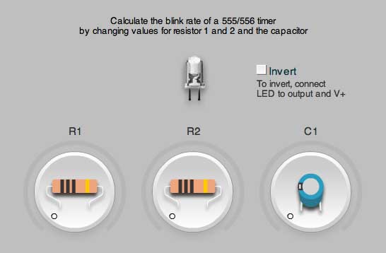
The 555 timing calculator that you can find in the electronic section of my refit app makes it easy to choose the proper resistor and capacitor value, although please be aware it’s still beta. Other calculators exist and this one is unique in that you can supply the time values and it will try to figure out the resistor and capacitor values.
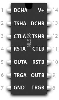 Now as wonderful as the 555 is, there are two types of blinking lights on most starships, and thus we’ll either need to use two 555 chips or the dual 556 chip, which can keep track of two time sequences, but needs 14 legs or pins so to do. As with most chips, the legs or pins are numbered counter-clockwise, starting with the upper-left pin. The top (or top left) of most chips are marked with a circle or an indent. The top right or highest numbered pin is usually power (V+) and can accept from about 4.5V to 18V (some say 15 to 16V). In my circuit, I’m supplying 6V. The ground or negative voltage is pin 7 or the bottom left pin. (On a 555 chip, ground is the top-left pin or pin 1.) Pins for the two timing circuits, A and B, run along the left- and right-hand sides of the chip.
By the way, I should mention these chips are dirt cheap. Even buying them one at a time at RadioShack, you’ll spend about $2 for the 555 and $2.50 for the 556.
The schematic
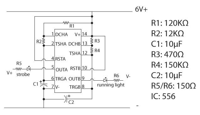
 This schematic shows the two circuits and rather than depict the chip in the simultaneously logical and non-sensical method of grouping common pins, I followed the actual layout of the chip. Actual physical connections, incidentally, are indicated by black dots. Wherever you see a little hop, it means the wiring crosses but does not connect. In both circuits, notice that the discharge (DCH) pin connects to pin 14 (V+) by way of the resistor, threshold (TSH) connects to discharge, also by way of a resistor, and trigger (TRG) connects to ground (V-) by way of the capacitor. Additionally, reset (RST) jumpers or connects to V+ and trigger jumpers to threshold.
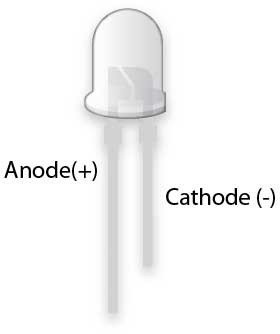
The most important thing to note is that the for the strobe circuit, the anode, positive or longer leg of the LED is connected to V+, while for the running light, the cathode, negative or shorter leg of the LED is connected to ground or V-. If you connect the strobe LED to ground, you see a light that stays on about a second and winks off for a fraction of a second.
The values of the various components is shown on the right and were actually chosen by using a variable resistor to get the timing to my liking. I’ll talk about that in a later post. It looks complicated (it does to me, at least), but it’s a lot more understandable if you build it on a breadboard.
Or, you can watch an astable circuit being built on a 555 chip here, with accompanying mellow music.
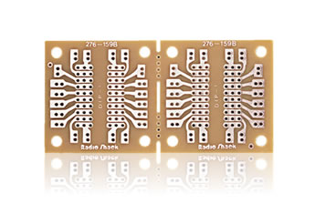
In the next post, I’ll show how you how to build the running lights/strobe circuit on the board shown below.