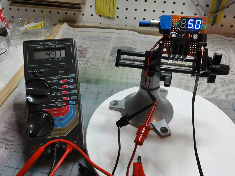
Variable power supply

As part of my 2014 resolution to learn enough about electronics to be dangerous, I’ve built a variable power supply to use on my breadboard projects based on a design I found at instructable.com. (If you’re not familiar with breadboards, it’s a quick way to test an electronic circuit without soldering all the components.)
In the past whenever I’ve embarked on a new project, I’ve spent an inordinate amount of time searching for batteries or some sort of case to hold the batteries. And at some point in the project, I’ll find that a battery is dead or that the battery clips don’t make contact and I’ll suspect I have a problem with the circuit when actually I have a malfunctioning power supply.
This simple board, however, gives me a regulated power supply that can be adjusted from 1.2 to about 16V, using an LM317T voltage regulator and a 5KΩ potentiometer. It’s a compact design that makes construction a little awkward, although I’ll also give you a design that has (and wastes) a lot more room.
Parts
LM317T variable power supply (also available at RadioShack)
Heat sink designed for TOS-220 chip style
(2) 100µF electrolytic (aluminum) capacitor rated to 25V
(2) .1µF ceramic capacitor (obtained from my parts bin)
5KΩ potentiometer
Keedox 0-99V digital DC Mini Blue 0.36” display
2.5mm I.D. / 5.5mm O.D. male barrel-type power connector (on board)
2.5mm I.D. / 5.5mm O.D. female barrel-type power connector (connected to transformer)
Printed circuit board
120VAC/13.5VDC 850mA RadioShack transformer Cat. No. 16-126 (actually outputs 18V, no longer made)
Tools
Soldering iron
Small screwdriver
Pin vise with drill bits
X-Acto knife
