Variable power supply
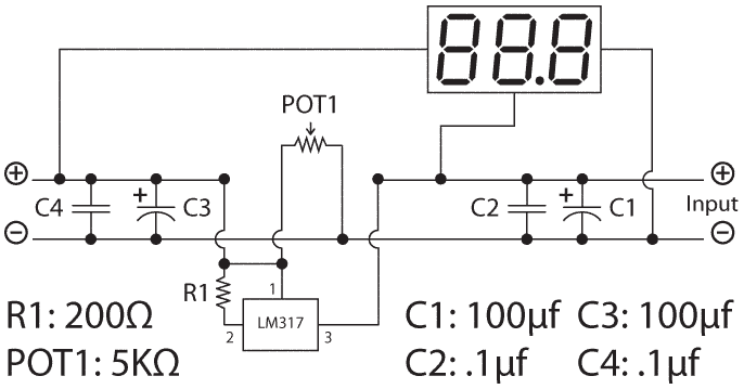
The schematic
WARNING: I’m an electronics newbie and I often don’t know what I’m doing. This power supply, for instance, doesn’t have a fuse to prevent a short circuit or a diode to prevent someone connecting positive to negative. If you hear your transformer make a humming sound or smell something burning, then turn off the power immediately. Other warning signs are a voltmeter that reads OV output or an unlit display.
Proceed with caution. Soldering irons are hot. Soldering fumes are toxic. Wear a mask and eye protection when drilling or cutting the circuit board.
My apologies for the somewhat odd layout of this schematic, but it’s intended to more or less match the layout of the actual board. The input is on the right and the output on the left. Two rails or busses travel the width of the board, but notice the break in the positive bus after the input voltage is supplied to the LM317. Also notice that the digital display also takes its supply here. The KEEDOX board runs on 4.5–30V while the LM317 outputs from 1.2 to 37V, so at the lower end, the output voltage would not be enough to run the readout. The output voltage is sampled by the readout right after C4.
There are two sets of capacitors that (according to EngineeringShock.com (whose circuit I’ve copied) help smooth out the input voltage and also the output voltage. C1 and C3 are smoothing capacitors and C2 and C4 are decoupling capacitors.

