
Variable power supply
Board layout
Here are illustrations of how I’ve designed my board:
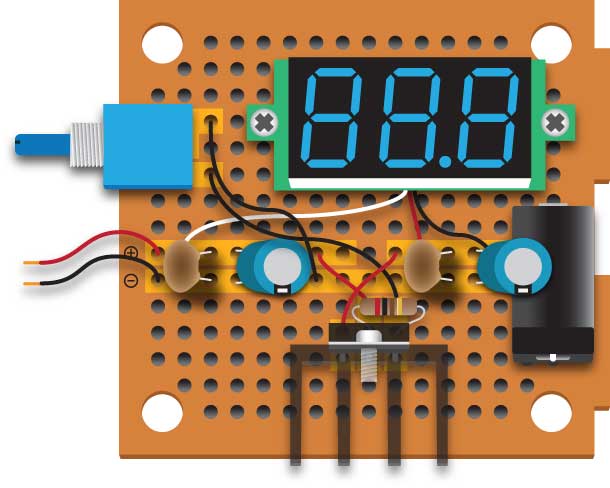
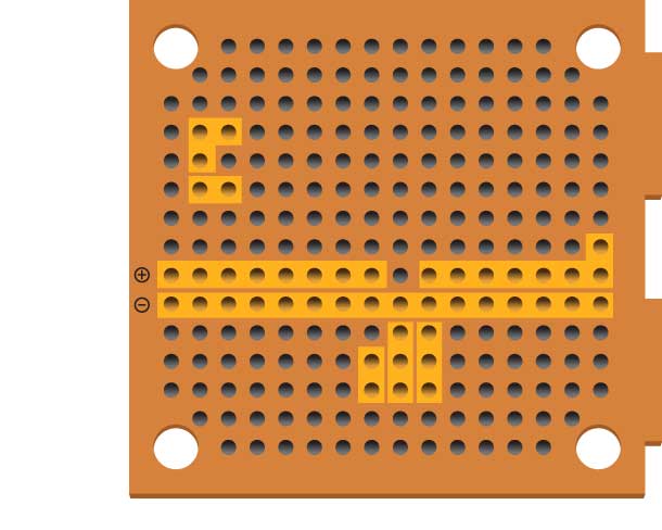
The second image shows the buss rails that are actually on the backside of the board, but shown here on the front. When assembling the board, I’d suggest starting at either end of the buss strips first, soldering the input jack on the right to the buss and then the power leads on the left, then adding the capacitors and then soldering the jumpers that connect to the LM317 and the potentiometer and then connecting the digital display. Finally, add the LM317 and the potentiometer. If you add the three large components first, it will make it much more difficult to attach the capacitors and the jumpers.