
Variable power supply
Final thoughts
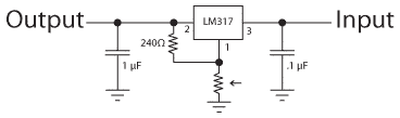 Remember, I really don’t know what I’m doing. I just look at other people’s schematics and adapt them for my own use. You can buy a kit for just $6.75 at EngineeringShock.com (although this version no longer includes the digital display). I also suspect this board has twice as many capacitors as are needed. If you look at the LM317 data sheet, it shows a typical circuit that has a .1 µF capacitor at the input and a 1 µF capacitor at the output. If don’t need a variable power supply, you can simply connect two fixed resistors, as shown in this YouTube video. Of course, you’ll need to do some math to figure this out.
Frankly, I’m not sure that I need any capacitors at all and curiously you’ll find that many tutorials suggest that the value of the larger capacitor is basically up to you. It will take a little longer for a larger capacitor to fill up but I think we’re talking microseconds. The 100µF electrolytic capacitor I used is probably overkill. I’ll probably never know how useful (and properly placed) my capacitors are unless I connect it to a oscilloscope, a piece of kit that’s still in my future.
One change I’ll probably make to my board is to mount it to a piece of scrap wood, heavy enough to keep it from sliding around. It’s very easy to accidentally turn the potentiometer knob and you wouldn’t want to connect 16V to an integrated circuit.
I will try to remember to update this post as I use this power supply in future projects. Finally, I offer an exciting video of me turning the knob on my power supply and comparing the digital readout to my multimeter display.