Deflector dish glow
After puzzling out how to use a transistor to turn on multiple LEDs using the output from a 555 chip, I’m now in search of how to change the light coming from the deflector on a starship from amber to blue. I was asked by another how to do this and I had no clue, other than to buy something like the tenacontrols board that does just that (see video below). I’d never really intended to light my refit this way, content with just the blue glow indicating the ship was at warp, but it seems all the rage these days, especially with the convenience of two color LEDs such as is offered at hdamodelworx.
I naturally reached for a solution using a 555 timer and started searching for a similar circuit but had no luck. There are myriad circuits for fading an LED up and down (putting the 555 into astable multivibrator mode) and often these involve a honking big capacitor, like 2200μF, to make the glow gradual enough. (Using an op-amp should also accomplish this, but then you have two chips.) There are better circuits that use a transistor as an amplifier, requiring the use of a less bulky capacitor, but there’s an essential problem with this type of circuit: the glow continues to cycle.

What we really want is a one-time cycle. The deflector should gradually glow to amber and stay at the illumination until the user changes it to blue. The amber should slowly fade while the blue builds. And then the reverse when the user switches it back to amber.
Of course one could put the 555 into monostable mode, making it a one shot with timer, but you couldn’t then get it to do the fade. Perhaps it would be possible with two 555s or a 556, but there’s still the problem that the fade you’d get from a 555 would be a fade up and down, whereas what we want is a fade up and stay on, and then a fade down and stay off.
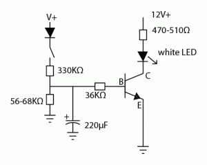
This could be done with a micro controller, and I may eventually just do that for whenever I return to my refit. The cost of an ATtiny micro, for instance, is well under $10, and I suspect something like it drives the tenacontrols board. I still have a perverse desire to attempt this old school, however, and I searched YouTube until I found the video above. It gradually lights an LED and maintains a maximum brightness until power is removed, whereupon it gradually fades. It’s little more than a couple of resistors, a capacitor and a transistor. I think the diode is just there to make sure the polarity is correct and please correct me if I’m wrong.
To get the amber to blue glow, then, I envision a SPDT or three-way micro switch. Throw the switch full left and the amber LED slowly glows, throw it to the middle and the amber LED fades and the blue one glows. Throw it full right and either lit LED will go out. Of course this means two identical circuits with two transistors and two capacitors and six resistors (not counting the limiting resistors for the LEDs), but still manageable I think.
You can probably find other similar circuits if you search for car dome light circuits. I’ll attempt to breadboard this circuit and post a circuit diagram. I don’t have an amber/blue LED, so I’ll just use an orange and a blue LED and I hope I have a three-way switch somewhere.
Finally, here’s another video that adds a potentiometer to make it easier to change the speed of the effect:
I’m sure there’s math involved to get just the right timing, and maybe my friend Hung will chime in what that information. I suspect that R1 and the capacitor represent just a simple R-C circuit, and if so, this page should give the math for how long it takes for the glow to reach the maximum. Being rather stupid about this, I guess the transistor is being both a switch and an amplifer.
