Deflector dish glow update
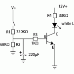
Above is the circuit I created to simulate the amber/blue deflector dish glow of a Federation starship. Although the timing isn’t perfect, I find it acceptable and it’s based on the circuit I found at the electronicsNmore YouTube channel (see previous post). Below is a modified schematic showing the actual values I used for the components.

Duplicate the circuit for amber and blue and a three-way switch to go between impulse and warp. (A Facebook friend brought this amber/blue switch to my attention.) I didn’t have a bi-color LED handy so I used two white LEDs colored orange and blue. A white LED can be colored quite easily by lightly scuffing it with 320 or higher grit sandpaper or file and then marking it with a Sharpie.
The 330Ω limiting resistor for the LED is pretty low; it should be 470Ω, but using a 330K resistor for R1 will limit the voltage that flows through the collector and into the LED. If you use a smaller resistor for R1, the LED will be brighter but the capacitor will fill more quickly.
A limitation of this is that the first time you complete the circuit, it will take a relatively long time for the capacitor to charge enough to light the LED. If you cycle the circuit quickly, it won’t take as long for the glow to begin because the capacitor won’t have completely discharged. Actually, though, I rather like this because it inherently duplicates the startup sequence we see in the movies.
