
Lights and sound
There are a mind-numbing number of lights on the Enterprise refit and, of course, it’s up to you whether to include every light and lighting effect. If all you want to do is get the collision strobes and navigation lights flashing that’s perfectly understandable. My goal was more ambitious and if you’re reading this, I suspect yours as well.
Spotlights
One of the most maddening lighting effects on the refit are the spotlights. I’m sure anyone who is attempting to light a refit are already aware of the problems, but to summarize, in some places it’s very difficult to make a spotlight shine on that spot—or even physically impossible. Most of the spotlight effects on the filming model were accomplished with external lighting. How you achieve this impossible lighting is up to you, but most people resort to the Raytheon effect. Google it if you’re unfamiliar, but it’s essentially simulating spotlight glows with internal lighting shining through a mask.
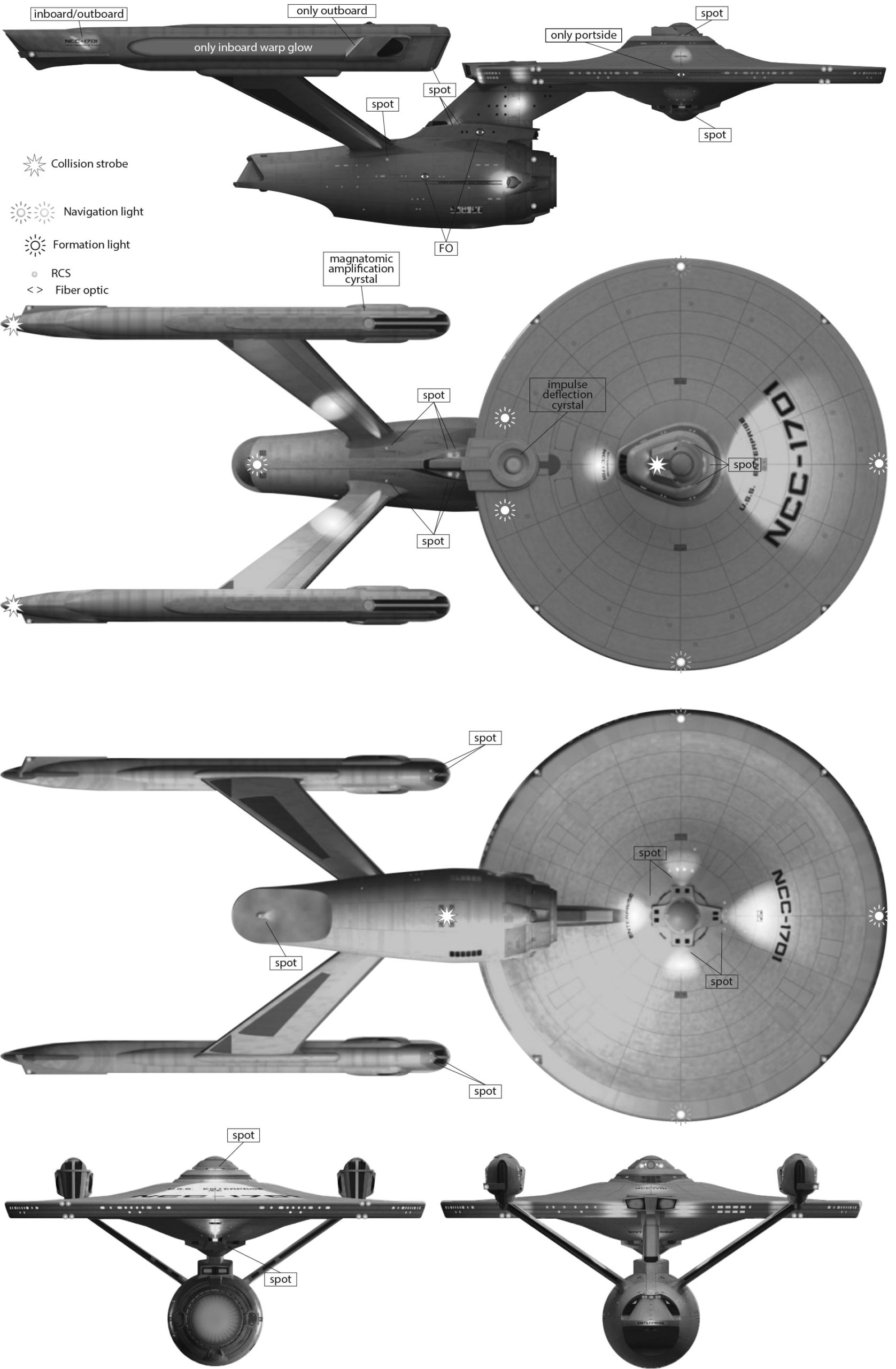
I count 25 spotlights or spotlight lighting effects on the model, but if you follow the spacedock lighting sequence, you can group these lights into seven locations. There’s an excellent lighting reference on YouTube that shows the exact time the spotlights activate and in what order.
Nacelle pylons
There are spotlights shining on the outboard and inboard sides of the nacelle pylons. Unfortunately, the angle of the spots could not possibly produce the round glow effect seen on the inside of the pylons.
Nacelle front
There are two spotlights at the front of the nacelle. The outboard spot probably shines on the edge of the saucer near the RCS thruster quadrant. The inboard spot probably shines just to the outside of the impulse engines.
Saucer pylon
There are two spotlights on either side of the base of the pylon that connects the engineering hull with the saucer. One is certainly responsible for the large oval lighting effect seen on the side of the pylon, but the angle of the spotlight to the pylon could not possibly produce that effect. The other spotlight seems to shine up to the impulse engines, however that conflicts with the inboard spot at the front of the nacelle, which also seems to shine on the impulse engines.
Nacelle rear
There are two lighting effects both inboard and outboard on the registry at the rear of the nacelle. There’s no logical source for this lighting except for something like electro-luminescent paint?
Saucer above
There are three clearly identifiable spotlights at the base of the bridge (A deck) that shine port, starboard and forward. It’s difficult to get these lights to actually shine on the saucer as shone, but it is just possible by slightly increasing the height of A deck. That’s the technique used by Boyd Crompton at TrekWorks. To truly reproduce what’s seen in the movie, however, requires the Raytheon effect.
There is no visible source, however, for the spotlight that shines on the registry aft of the VIP lounge and will require the Raytheon technique to reproduce.
Saucer below
Fortunately, the source of the four spotlights that emanate from the planetary array on the underside of the saucer are obvious, however it is difficult to angle the lights to produce the movie lighting.
Engineering hull
There are spotlight effects on either side of the engineering hull shining on the Starfleet pennant, but there’s no logical light source. There’s another spotlight found on the underside of the engineering hull emanating from the bulge that’s the cargo bay tractor beam emitter (if we follow Mr. Scott’s Guide to the Enterprise). It shines on the large cargo hatch. Finally, there’s a spotlight shining on the name of the ship on the lip of the main shuttle bay with no logical light source.
Startup sequence
Based on the lighting reference mentioned earlier, you can see that in order:
- The spotlights at the base of the nacelle pylons light;
- then the spotlights at the front of the nacelles;
- next the spotlights at the base of the saucer pylon;
- the lights on the registry at the rear of the nacelles;
- the lower saucer spotlights;
- the upper saucer spotlights;
- and finally, the spotlights shine on the pennants on the engineering hull.
The RCS thrusters glow at step four when the registry is lit on the nacelles and I assume all the thrusters throughout the ship glow. The deflector dish also glows at step seven and I’ve decided that’s when the collision strobes and navigation lights should begin flashing. I’ve also decided that’s when the tractor beam spotlight activates.
Sources
Apart from the seeming impossibility of some of these spotlights, the biggest puzzle is the source of the lighting of the impulse engines and the Starfleet pennant on the engineering hull. In the YouTube lighting reference referred to earlier, it’s clear that both the outboard and inboard spotlights at the front of the nacelles light at the same time. Is the inboard spotlight shining on the impulse engines?
Two seconds later, the spotlights at the base of the saucer pylon light. The forward spot seems to light the pylon while the rear spot seems to shine on the impulse engines.
I think it makes more sense that the inboard spot on the nacelle shines on the engineering hull and the rear saucer pylon spot lights the impulse engines.
Which, of course, conflicts with the lighting of the engineering hull pennant at 11 seconds in the video. The only way to reconcile this is to either assign the pennant lighting to luminescent paint or decide the inboard spot does not light at the same time as the outboard spot.
That decision is up to you. If you decide to light the two forward nacelle spots at different times, you’ll need two wires going to the nacelle for that purpose.
RCS thrusters
There are far more RCS thrusters than the eight pins on the 74HC595 chip that is used to light them. However, if we group the thrusters, we can come up with eight. The thrusters on the saucer, for instance, are already grouped into four quadrants, even if each quadrant has separate upper, lower and side thrusters. We can do the same for the thrusters at the ends of the nacelles and just treat upper, lower and side thrusters as a unit. That gets us up to six.
There are four thruster locations that ring the deflector dish, but we can group these into port and starboard thrusters, for a total of eight groups.
Now, as shown in the startup sequence, the thrusters are always faintly lit. It’s up to you how you want to handle this, but I’ve decided that where possible I’ll run fiber optic to each thruster from the LED tape window lighting or where necessary I’ll run an always on LED. What is not possible, however, is to match the lighting of the RCS thrusters in step four. They will appear lit the moment power is supplied to the circuit.
Window lighting
Window lighting is provided by LED strips placed throughout the ship. Unfortunately, there’s no way to control the intensity of the LED strips because we’ve run out of pins on our two processors. We would need a PWM pin for this purpose, but that would require reassigning a pin (perhaps the second phaser pin) and some shuffling to make a PWM pin available.
There are a few workarounds, however. If your power supply adapter (the wall wart) can be set to different voltages, you can select 9V instead of 12V. It will be a little bit dimmer, but probably not much. You could buy a dimmer for the LED strip, but it might look out of place, especially if the hardware is obtrusive. (Dimmers with a remote control would be preferable.)
Or, if you have a spare 555 timer, you could make a PWM dimmer. Because there’s no room for it on our boards, you’ll need a separate perfboard. You’ll end up with a potentiometer and a MOSFET connected to a 555 to dim the LED strips.
Of course, at $1.30 for a 555, you might consider just buying another ATtiny85 for $1.64 (these are prices for individual components at Mouser.com). You’d only need two of its five pins, leaving you three more pins to add additional functions. You could even add a sensor to adjust the intensity of the LED strips depending on whether it’s day or night. Or, you can just live without the ability to dim the LED strips. The 555 solution, however, is pretty common and it wouldn’t hurt to learn its many uses. You can learn more about this in the video below or read about it here.
Photon torpedoes
You’ll need two LEDs to represent the photon torpedoes. You might find rectangular LEDs that would work or you could square off standard round LEDs to fit.
Phasers
There are 12 phaser emitters on the refit, but we only have two pins dedicated to lighting them. If you decide to only light two, I suggest picking one above and one below. If you decide to route the phaser pin output through transistors, you could, of course, light several LEDs from each pin.
PWM lighting
Several of the light sources on the model are connected to the impulse and warp pins on the ATtiny, via either a transistor or a MOSFET. The deflector dish and the impulse deflection crystal are connected to both. The magnatomic amplification and the warp nacelles are connected to the warp pin. And the impulse engine is connected to the impulse pin. If you decide to use the 555 timer mentioned above, the window lighting would also be controlled by PWM.
Additional lighting
The additional lighting on the ship is of two types, fiber optic and individual LEDs. There is a docking port aft of the bridge, two on the docking ports on either side of the engineering hull, one on the port side of the saucer (it is rectangular instead of round). You’ll probably have to rely on fiber optic to light them, although the rear of the bridge is clear plastic and you could scratch a light bleed through the paint to reproduce the effect. The main shuttle bay entrance also has a number of lights that might also require fiber optic lighting or SMDs.
Shuttle bay landing lights
One feature that Enterprise-A modelers might want to include is the shuttle bay landing lights seen in the fifth Star Trek movie. This is basically just an LED chaser sequence that could be simulated with the 74HC595 that’s already being used to light the RCS thrusters.
Your options are to re-purpose the 595 for this—lose the RCS thrusters to get the landing lights. You’ll still need to free up an additional pin that’s connected to a button if you want to trigger the effect, although you could just make this a random feature activated by the sketch.
Or, you could daisy chain another 595 to the first, giving you and additional eight outputs. This doesn’t require additional pins on the ATMega328 other than the aforementioned button pin. It’s pretty simple and it’s addressed in the More about chapter. Again, you could either tie this to a button or include the feature in the sketch.
Another option is to power the landing lights with a 555 timer connected to a 4017 decade counter. A decade counter can sequentially power its ten output pins based on a clock signal sent by the 555. There’s more about the 4017 in the More about chapter.
Additional microprocessors
Many of the lighting conundrums presented here could, of course, be reconciled by adding more microprocessors or using larger microprocessors (with more input and output pins). Instead of an ATtiny and ATMega you could opt for two ATMegas. Or use an Arduino Nano, which although it’s based on the ATMega328, uses the surface mount version of the chip that has additional pins.
So really it’s up to you what features you want to include or what microprocessors you use. This guide is just a starting point.