
Support socket for Enterprise refit
One of the reasons I’ve delayed for so long in building my 1/350th Enterprise refit is that I could never figure out how to support the model. I’ve always wanted a Enterprise that would appear to be floating in space, but I had no idea how to accomplish this …
… until I got my Prusa Mini+ 3D printer. I realized that I could make a 3D printed insert or socket into which I could slide a metal bar that could hold the weight of the model. Fortunately it wasn’t too difficult to design because the engineering hull is basically a perfectly circular, tapered cylinder. With a caliper, I measured the length of the chord of the circle running along the two bulkheads and the depth from the chord to the bottom of the hull (on the inside).
In Autodesk Fusion 360 (free to use for hobbyists), I drew two concentric circles that were created using those measurements, moved them the appropriate distance apart, and then lofted a shape stretched between these two crescent shapes. It worked out surprisingly well, even though I didn’t know the diameters of the circles. I had no direct way to measure the diameter because it would require taping together the four segments of the engineering hull, measuring the width of the hull and subtracting the doubled value of the thickness of the plastic. And the jaws of my small caliper wouldn’t be long enough to do this anyway. I don’t have any compasses or calipers with curved legs.
But Fusion 360 can draw an appropriately dimensioned circle based on the length of the chord and the length of a perpendicular line drawn from the midpoint of the chord. It does this through a series of constraints that are too complicated to explain here.
Of course my measures weren’t exact (it’s hard to get the exact depth from the bulkhead to the inner surface of the hull) so once I had ballpark figures for the diameters of the circles, I used a Cricut cutting machine to cut a range of circles of different diameters and test fit them against the front and rear bulkheads. With these measurements, I was able to dial in the perfect diameters of the circles that were used to create the lofted shape in Fusion 360. The test piece I printed fitted perfectly.
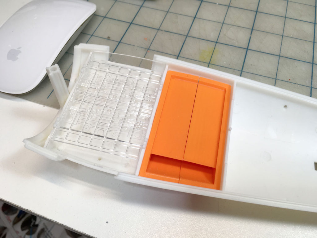
In Fusion 360, I created an open shell of the lofted piece and then subtracted the opening into which a C-channel metal bar will be inserted. I also needed to subtract a spot where the plastic post on the bottom of the hull supports the arboretum. This second Boolean subtraction also makes it possible to run wires to the collision strobe at the bottom of the engineering hull. I probably will avoid wiring the bottom cluster of four phasers.
I know that the center of mass of the model is probably where the arboretum is, but I hope the support socket will be sufficient to hold the model without undue stress. The socket will eventually be epoxied into place.
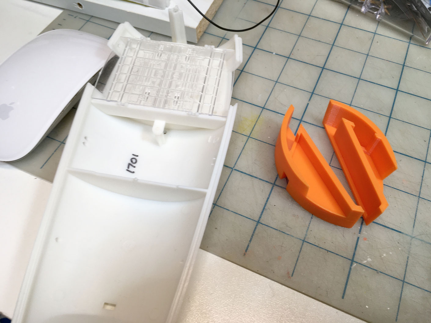
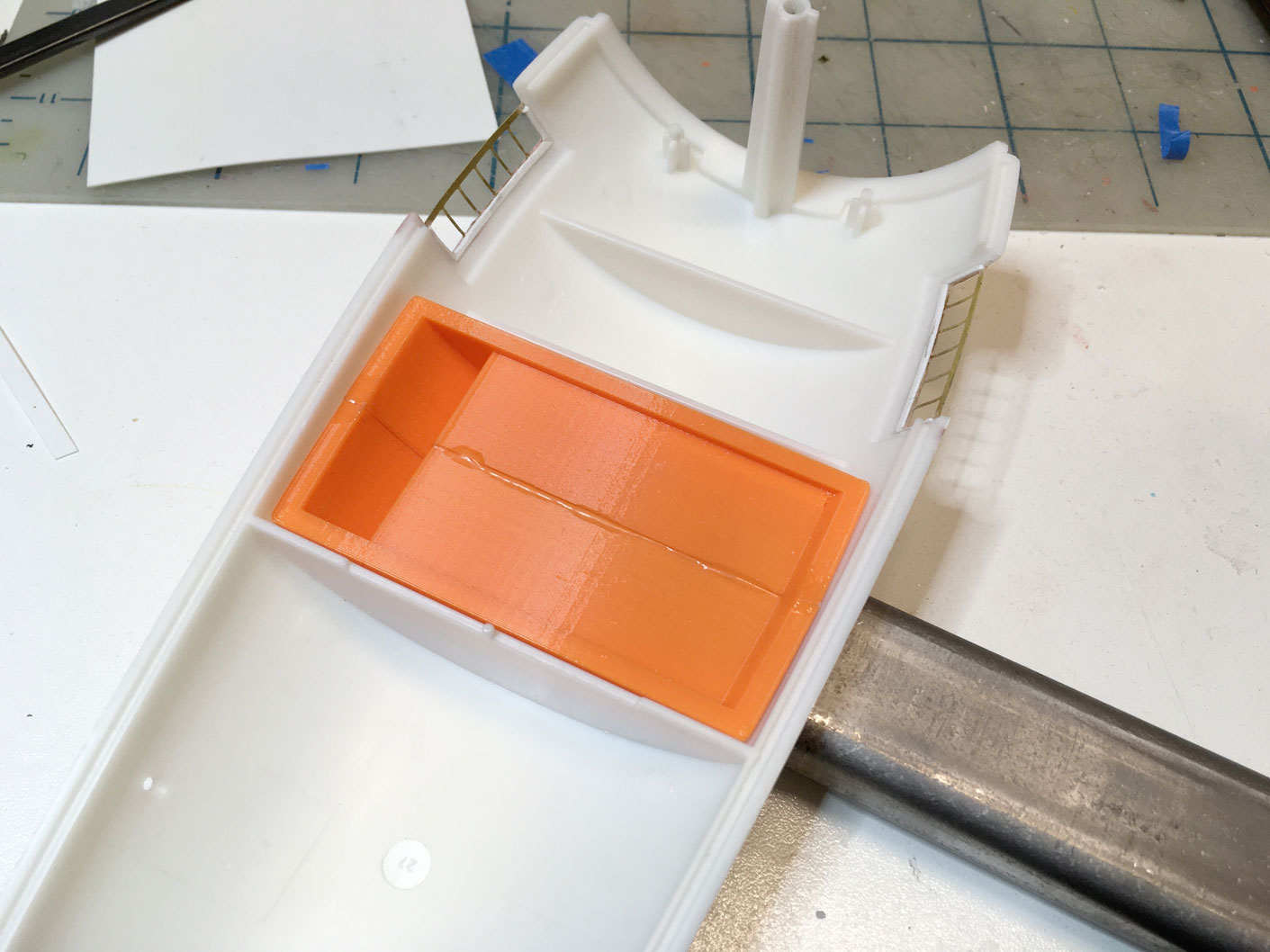
Because there’s a large void for the C-channel, it would be difficult to print the socket as a single piece without supports. (I tried printing a single test piece with supports, but it was very tedious to clean up.) So instead, I printed the socket in two halves and epoxied them together. Then I had the daunting task of opening a hole in the plastic of the engineering hull that matches the opening in the printed socket. It’s a fairly large hole and the top of it is just below two portholes on the starboard side.
But when I finish, the metal C-channel will disappear into a wooden plaque and be bolted into place. The plaque will be painted black, perhaps with a starscape, and hung on a wall. Viewing the port side of the ship, it will appear to be hanging in space. Or, that’s the hope.
The plastic socket printed in about two hours, fairly long because I used a high infill value. Wiring to the ship will run along the C-channel, into the socket and then into the ship through the open end of the hole where the C-channel sits. I am presently planning on mounting the circuit boards inside the ship, meaning I’ll only need to run five wires to the ship. If I keep the boards outside, I’d need to run 27 wires to the ship.
The end of the C-channel will be cut at 45° to penetrate further into the socket and create a larger mating surface. I’ll probably clad the C-channel in styrene and paint it black to disappear into the black plaque.