
More About …
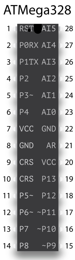
Before we begin, I thought I’d warn you about a common “gotcha” you might encounter when dealing with integrated circuits. This involves the numbering of the pins or legs on the ATMega328 and the ATtiny85. On an IC, legs or pins are numbered sequentially in an anti-clockwise fashion starting from the top left of a chip. There’s usually an indent on one end of a chip to indicate the top, and often there’s a circular depression to indicate pin one.
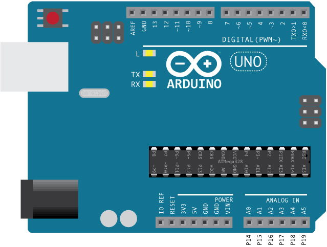
However, the physical numbering of pins rarely has anything to do with the pin assignments you’ll specify when writing a sketch. In the Arduino Uno shown above, you’ll see the numbered header pins at the top and bottom of the board. Digital input/output pins 13–0 are on top from left to right, and in the bottom right corner, you’ll see digital I/O pins 14–19, which also serve as analog input pins A0–A5. These are the numbers you’ll refer to in a sketch, not the physical layout numbers.
The Arduino IDE knows which pins do what based on the microprocessor you select. You’ll see this process in the Programming the Microprocessor chapter.
Looking at the ATMega328 chip on the Uno board, you’ll see that physical pin one is in the upper right. The top of the chip is facing right. The second pin corresponds to digital I/O pin zero (which also serves as the receive pin) at the right of the top header row. Physical pin 14, in the bottom left corner of the chip, corresponds to digital I/O pin 8. Physical pin 28 is actually digital I/O pin 19 or analog input pin A5.
Fortunately you can write a sketch that runs on the Arduino Uno, upload that sketch to an ATMega328, and it will run without a problem because the internal pin assignments are the same. That’s not the case with the ATtiny85, and we’ll look at that later in this chapter.
Arduino Uno
Let’s take a closer look at the Arduino Uno. The gray box on the upper left is the USB port that connects the Uno to a computer. The Uno gets 5V from the USB cable. Below the USB port at bottom left, you’ll see the external power supply jack. You can power the Uno with a 7–12V external adapter (wall wart).
As mentioned before, you’ll see the header pins across the top and bottom. The top row contains a GND pin and digital I/O pins 13–0. You can ignore the AREF pin. Just below the left side of the header pins you’ll also see three LEDs. The top one is connected to pin 13, and that’s the LED you’ll see blink if you upload the beginner “Blink” sketch to the Uno. The other two LEDs correspond to pins 0 (RX) and 1 (TX). You’ll see those flash when you upload a sketch to the Uno.
The bottom header row includes reset, 3.3V, 5V, GND, V-in and the five analog pins. You can ignore the IOREF pin. Although there’s a reset button on the Uno, it may be beneficial to have an external button wired to the pin, if you have enclosed the Uno. You won’t need the 3.3V pin. The 5V pin is useful for supplying power to breadboards. And you can never have too many GND pins. V-in is only valid if you’re using an external power supply, so if you’re supplying the Uno 12V, you’ll find 12V at this pin.
Arduino IDE
You will need to download the Arduino integrated development environment or IDE in order to program the Arduino. It’s open source and free and should work with any Arduino, even those not made by the Arduino company. It can also program chips like the ATtiny85 or ATMega328. When you install the Arduino IDE, it will create an Arduino folder on your computer where you can add libraries such as the ones used here.
You’ll need a USB cable to connect your computer with the Arduino, but that cable differs if you have the Arduino Uno (type A/B) or Arduino Nano (type A/mini-B). (Of course, the cable will differ if your computer doesn’t have a type A connector.)
ATMega328
As mentioned earlier, the microprocessor on the Arduino Uno is the ATMega328, and you might think why not just use the Uno to power the starship. You certainly could, but a Uno costs $23. The chip is priced about $2. So, if you’re lighting several starships, it makes economic sense to buy the chip. The chip also takes less room than the Uno, although admittedly once you’ve mounted the chip on a perfboard and added a voltage regulator, that advantage disappears.
Connections
At a minimum on a breadboard or solderable perfboard, you will need to connect the reset pin (pin 1) to ground with a 10KΩ resistor; pins 7 and 8 to V+ and GND; and pins 21 and 22 to 5V. Because we’re using an external clock crystal across pins 9 and 10, we’ll also connect those pins to ground with 22pF ceramic capacitors. We could actually get by with even fewer connected pins and no external clock, but I advise against that.
Numbered pins 2 and 3 correspond to pins 0 and 1 on the UNO. These are the serial read and write pins, so they’re unused if you want to have serial communication with the ATMega. We don’t care about this, so we’re using these two pins as digital output to fire phasers.
Numbered pins 4–6 and 11–14 are digital output pins connected to the ULN2803A and control the activation of the spotlights. These pins correspond to pins 2–4 and 5–8 on the Uno.
Numbered pins 15 and 16 fire the torpedoes, and they’re the same as pins 9 and 10 on the Uno. Notice on the picture of the chip there’s a ~ next to the pin number, indicating these are PWM pins.
Numbered pins 17–19 connect to the Adafruit FX Sound Board. Pin 17 connects to the reset pin of the sound board, 18 to the RX pin of the sound board and 19 to the TX pin of the sound board. These numbered pins correspond to pins 11–13 on the Uno.
Numbered pins 23–28 are analog input pins, although we only use pin 28 for that purpose. They correspond to pins 14–19 on the Uno. Numbered pin 23 is used as a digital input connected to the button that triggers the weapons fire. Numbered pin 24 is used as a digital input connected to the Act pin of the sound board and detects whether a sound is playing.
Numbered pins 25–27 connect to the clock, latch and data pins of the 74HC595 and are all digital output. What’s mysterious here is that pin 27 is not a PWM pin, and yet it’s sending out serial data. I have no idea what voodoo makes this possible.
The last numbered pin is 28, and it’s connected to the warp pin of the ATtiny85. Read more about that in the chapter on PWM.
Of course, in our sketch, we don’t refer to the physical pin numbering, but rather the numbers you see on the image on the previous page, within the body of the chip. However, one of the advantages of the ATMega328 is that a sketch written for the Uno runs without a problem on the ATMega because they use the same internal pin numbering.
Incidentally, there are a number of flavors of the ATMega328. Make sure you order the long, 28-pin version of the chip rather the square, surface mount version.
| ATMega328 | |||
|---|---|---|---|
| 1 | Reset | Warp detect: AI5(P19) | 28 |
| 2 | P0(RX): phaser | data: AI4 | 27 |
| 3 | P1(TX): phaser | latch: AI3 | 26 |
| 4 | P2: spotlight | clock: AI2 | 25 |
| 5 | P3~: spotlight | sound detect: AI1 | 24 |
| 6 | P4: spotlight | weapons button: AI0 | 23 |
| 7 | VCC | GND | 22 |
| 8 | GND | AREF | 21 |
| 9 | CRS: external clock | VCC | 20 |
| 10 | CRS: external clock | sound board TX: P13 | 19 |
| 11 | P5~: spotlight | sound board RX: P12 | 18 |
| 12 | P6~: spotlight | sound board reset: P11~ | 17 |
| 13 | P7: spotlight | torpedo: P10~ | 16 |
| 14 | P8: spotlight | torpedo: P9~ | 15 |
ATtiny85
This eight-pin chip has most of the capability of the ATMega, but with far fewer input and output pins. (It does has an 8MB RAM limit, compared to the 32MB limit of the ATMega.) Unfortunately, because of this, we can’t use the same pin numbers in a sketch written for the Uno or ATMega328.
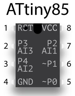
Numbered pin 1 is the Reset pin. Numbered pin 2 is actually either digital pin 3 or analog input pin 3 (A3) in a sketch, and it powers the navigation/formation lights. Numbered pin 3 is digital pin 4 or A2 in a sketch, and it is connected to the button that switches between impulse and warp lighting. Numbered pin 5 is PWM capable pin 0 and provides the impulse lighting signal. Numbered pin 6 is PWM capable pin 1 and is the signal for warp lighting. Finally, numbered pin 7 is either pin 2 or analog input A1. Numbered pin 8 connects to 5V. Numbered pin 6 also connects to numbered pin 28 of the ATMega.
| ATtiny85 | |||
|---|---|---|---|
| 1 | Reset | VCC | 8 |
| 2 | AI3(P3): nav lights | strobes: AI1(P2) | 7 |
| 3 | AI2(P4): warp button | warp: P1~ | 6 |
| 4 | GND | impulse: P0~ | 5 |
Adafruit FX Sound Board
My use of the Adafruit FX Sound Board is one of the major differences between my lighting circuit and that of Trevor at Ostrich Longneck. He connects the ATMega to an SD card reader, which has an SD card loaded with sound effects. Although we’re reading from the SD card, we’re playing the sound using the audio output of the ATMega, which isn’t very good. Sound effects like firing phasers and torpedoes is acceptable, but music sounds terrible.
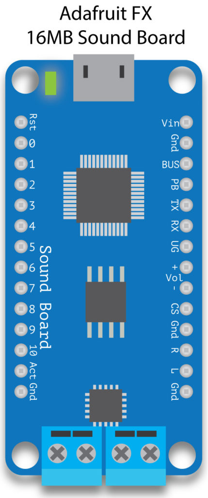
Instead, I opted to go with the FX Sound Board, which is actually a stand-alone music player, capable of playing MP3 quality audio. It’s available with either 2 or 16MB of onboard memory, and with/out an amplifier. I bought the 16MB version with onboard amp.
The board can be used in trigger mode, where you connect buttons to 11 trigger pins, or in serial mode, where you connect a microprocessor to the RX and TX pins. We’re using the latter option because we want to play sounds enabled by the sketch.
I’m not really sure which is the top or bottom of the board, so I’ll just identify the labels on the board. Vin (upper right) connects to 5V and GND connects to ground. You’ll also want the UG pin to connect to GND, which tells the board to use UART or serial control. RX connects to numbered pin 18 on the ATMega328. TX connects to numbered pin 19 on the ATMega. The reset pin (upper left) connects to numbered pin 17 on the ATMega, and finally Act (bottom left) connects to numbered pin 24 on the ATMega.
The screw terminals at the bottom connect to external speakers. You can use the R and L pins to connect to speakers, but you’ll need an amplifier. The volume pins don’t work in UART mode, nor do the numbered pins on the left-hand side.
At the top of the board, you’ll see a USB connector (micro B), which you can use to connect the board to your computer. The board will show up as a flash drive, to which you can transfer sound files. These sound files can be either in WAV format or OGG. The last may be unfamiliar, but it’s actually an open-source format equivalent to MP3. WAV files play immediately when called by the sketch, but there can be a slight delay when playing OGG files, because the file needs to be decompressed before playing. Fortunately, there’s a lengthy tutorial on how to use the sound board.
One last little detail about the sound board—all sound files must be saved in the old 8.3 format familiar to MS-DOS users in the 1980s. So, the sound file that plays when the ship goes to warp is named ####WARP.WAV. The four hatch marks make up the four missing characters.
Audio clips
Most of the audio clips I used for my sound effects were downloaded from trekcore.com, which has a large number of clips including music from the movies and TV shows. Also, special effects like phasers, torpedoes and warp drive sounds.
I don’t use the actual sounds from the first two movies for the phasers, torpedoes and going to warp. The phasers came from the original Star Trek series, the photon torpedoes from The Next Generation, going to warp from Voyager and dropping out of warp from The Next Generation.
The ambient bridge sounds came from Enterprise-B eight-hour clip on the ender4life channel on YouTube. The going to warp effect came from the thatSFXguy’s channel on YouTube.
I also created a little dockyard performance using the digitized voices on my Mac and the voices found at the IBM Watson Text to Speech demo. The latter is free and you simply paste in the text you want the synthesized voices to say. I also did the same with the high-quality synthesized voices that come with the Mac OS (they have to be downloaded separately). In order to record the spoken text, I downloaded the SoundFlower plug-in that makes it possible to record internal audio. I arranged the audio clips in Adobe Audition, but you could download the free program Audacity.
PWM
Pulse width modulation is a trick used to turn digital signals (either on or off, 0 or 5V) into something like analog values. We use PWM to make LEDs gradually fade up and down in brightness for both the deflector glow and warp nacelle glow effect.
The microprocessor achieves the effect of fading up and down by rapidly turning on and off the 5V signal on certain pins. For instance, if you want an LED to be 50% bright, you’d turn on and off the 5V signal for equal periods of time. Obviously, however, if you turned on the LED for one second and off for one second, you would perceive that as blinking on and off. If you turn the LED on for 1 millisecond and off for 1 millisecond, you just begin to perceive this as 50% brightness instead of rapid blinking. So, to fade up, we increase the on time and to fade down we decrease it. Or rather the microprocessor does this. We just need to write code that progressively changes the output value of the pin.
PWM offers 256 levels of brightness, using numbers from 0 to 255. Here’s an example:
analogWrite(9, 127);
We’re telling pin 9 to send out a signal that will equate to 50% brightness.
On the ATtiny85, two pins—0 and 1 (numbered pins 5 and 6)—are capable of PWM, and on the ATMega328, six pins have this—3, 5, 6, 9, 10 and 11 (numbered pins 5, 11, 12, 15, 16 and 17). You can still use these pins to send a purely digital signal:
digitalWrite(9, HIGH);
digitalWrite(11, LOW);
Analog input
Sort of the flip side of PWM is analog input. Certain pins can read an analog signal—voltage—and as the voltage varies, assign it a value between 0 and 1023. On the ATtiny85, three pins—2, 3 and 4 (numbered pins 2, 3 and 7) are capable of reading an analog signal, and on the ATMega328, six pins—A0, A1, A2, A3, A4 and A5 (numbered pins 23–38). The code to read an analog input looks like this:
value = analogRead(A0);
Notice I typed A0 for the pin number. If I wanted to read a digital signal on the numbered 23rd pin on the ATMega328, I would type:
value = digitalRead(14);
And value would be set to either HIGH or LOW. But numbered pin 23 is referred to as A0 when I want to analog read that pin.
There’s only one instance of analogRead in our starship lighting circuit, and it’s pretty unusual. We use the ATtiny85 to change from impulse (amber deflector lighting) to warp (blue deflector and warp nacelle lighting), controlled by a button connected to pin 4, numbered pin 3 on the ATtiny. Pins 0 and 1, used in PWM mode, control the amber and blue LEDs that signify impulse and warp.
The ATMega328 controls the sound effects of our lighting circuit, and it needs to know when someone has pressed the impulse/warp button connected to the ATtiny in order to play the appropriate sound effect. We do that with pin A5 (numbered pin 28) on the Mega, using it to detect when pin 1 (numbered pin 6) is above or below certain values.
Unfortunately, this is a little tricky. We’re trying to use an analog read pin on the Mega to detect the value of a PWM pin on the Tiny. Remember, if the PWM pin is sending out a 50% signal, half the time it’s sending out 5V and half the time 0V. So, the analog read can get very confused what is the actual value of the Tiny pin. We get around that by tying pin 28 on the Mega to ground with an electrolytic capacitor. I used a 100µf capacitor, which has the effect of blurring the signal enough (by constantly gradually charging and discharging) that the value can be read.
555 timer
The venerable 555 timer (introduced in 1971) is used in millions of places and before small microprocessors like the Arduino supplied the heartbeat of many a starship model. It can be used in three different modes—monostable, bistable and astable—but for our purposes we want to use it as an astable oscillator.

Going through the pins from top left, we have:
- GND, which connects to the ground of the power supply
- TRG, the trigger pin. In monostable or bistable mode, the trigger can be connected to a physical switch, but more likely to the output pin of another chip. In astable mode, pin 2 is connected to pin 6, because we’re using the value of the threshold pin to “pull” the trigger.
- OUT, or output is the HIGH or LOW signal produced by the chip
- RST, or reset, should be connected to V+ to prevent reset, so you’ll almost always see pin 4 connected to pin 8
- CTRL, or control, is rarely used. It usually goes to ground through a smoothing capacitor to prevent noise in the circuit.
- THR, or threshold, when it reaches a certain voltage, pulls the trigger in astable mode. It’s attached to a capacitor that gradually builds up the voltage that exceeds the threshold value. The speed at which the capacitor charges is controlled by a resistor connected to pin 7. If we’re using the 555 as a PWM LED dimmer controller, we’re using a potentiometer instead of a resistor.
- DCH, or discharge, is connected in astable mode to pin 8 with a resistor, and to pin 6 with another resistor. It’s the value of the resistors and the capacitor connected to pins 8, 7 and 6 that control the frequency of the clock signal produced by the 555 and the duty cycle of the signal—what percentage of the output is HIGH or LOW.
- VCC connects to the 5V power supply. Some users place a smoothing capacitor between GND and VCC, but it’s not necessary here.
I don’t have the knowledge to explain how the 555 works, any more than I can explain how the ATtiny or ATMega works. But I have read or watched a lot of explanations of how the 555 works, and although I don’t completely understand it, it has helped. Even a vague, fuzzy sort of knowledge makes it easier to understand what the pins do and how to wire them.
Trying to figure out the value of the resistors and capacitors connected to pins 8, 7 and 6 in order to get the desired duty cycle is tricky. Fortunately, there are online calculators for this.
Beyond using the 555 as a PWM dimmer, it can be used to produce many of the basic starship lighting effects. Two 555s—or more efficiently a 556, which is two 555s on a single 14-pin chip—can power collision strobes and navigation lights. Just like the ATtiny85, however, the outputs should control transistors that switch the various LEDs to a separate power rail. The total output of a 555 is only 200mA, which theoretically could power up to 10 LEDs, but the chip would probably run hot.
Another 555 coupled with a 4017 decade counter could also produce the spinning Bussard collector lights on the original enterprise. Or a 556 could power both the lights and drive stepper motors to recreate the spinning fan blade effects.
4017 decade counter
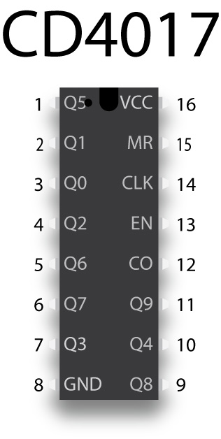
If you’d like to add the shuttle bay landing lights effects seen in the fifth Star Trek movie, you have a few options as mentioned in the Lights and Sound chapter. The easiest solution is to pair a 555 timer with the 4017 decade counter. You can see the complete circuit in the Examining the Board(s) chapter, but there are some complexities of the 4017 we’ll examine here.
Every time the 4017 reads a HIGH signal on the clock pin, it sequentially powers the ten output pins. The output pins are arranged haphazardly, as you can see in the pinout. If you need less than ten outputs, you’ll want to connect the unused pin to reset pin 15 to avoid a pause. So if you only need to light eight pins, tie pin 9 (Q8) to pin 15. It’s even possible to daisy chain 4017 chips to power any number of LEDs, but the circuitry become increasingly complicated and I’ve never attempted this.
LED basics
LEDs bring our starship model to life and you will use a couple hundred of them in your refit model. Most of the LEDs you use will be in the form of LED tape—a string of LEDs that are typically powered by a 12V power supply. But you’ll also use individual LEDs for the collision strobes and navigation lights and the floodlights.
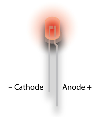
LEDs, of course, are light-emitting diodes and diodes have a polarity. Positive voltage must be connected to the anode (think “A-plus”) pin and ground to the cathode. The anode leg is usually longer and sometimes has a 45° kink just under the bulb. The cathode is shorter and sometimes the rim of the bulb has a flat spot on that side.
An output pin from the Arduino is supplying positive voltage, but sometimes that pin is connected to something like a transistor, and the “signal” coming from that transistor to the LED is the ground. This is the case for our collision strobes, navigation lights and the MOSFET that powers the warp nacelles. So, in this case, the signal from the transistor is attached to the ground leg.
LEDs almost always need to be connected to a limiting resistor or else they’ll burn out. The value of the resistor depends on the color of the LEDs and the voltage supplied to the LED. You can use Ohm’s Law to determine what resistor value to use, but frankly I just use online calculators to figure this out. An online calculator will ask for the voltage (always 5V in our circuit), the voltage drop of the LED (depends on the color and brightness), the current draw (usually 20 milliamps) and the number of LEDs, which is always one. Unfortunately, I’ve acquired LEDs here and there, so I’m not certain of the exact voltage drop or current draw of an LED, so I often use a higher value resistor than the one suggested by online calculators.
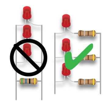
It always one LED because although we’re wiring LEDs in parallel, we’re still attaching a resistor to each LED. Don’t be tempted like I was to wire a single, high-value resistor in parallel with multiple LEDs, thinking I would save time soldering and use fewer resistors. If one of the LEDs fail, then the remaining LEDs will run a little hotter because that one resistor is insufficient. Then another LED will fail, and so on. Instead, you should wire a low-value resistor in series to each LED, while the LED/resistor pairs are wired in parallel.
By the way, most people solder connectors to the ground leg of an LED, but in fact you can solder it to either leg.
LED tape, incidentally, has built-in resistors that are perfect with a 12V supply, but still work, if not quite as bright, with 9V. LED tape, interestingly, are three LEDs connected in serial, but each three-LED group is wired in parallel. If one LED fails, all three LEDs won’t light, but the rest of the LEDs still work. This is why you can only cut LED tape every three LEDs.
To make my life easier, I often buy white LEDs and color them as needed. This way I can use the same voltage drop value. LED bulbs are so slick, however, they can be hard to color. It’s best to sand the bulbs with a fine grit sanding stick or spray a matte lacquer. Then I dip them in clear, colored acrylic or apply a permanent marker of the appropriate color, followed by a clear acrylic topcoat.
1N4001 Diode
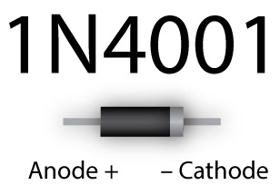
Diodes are very similar to LEDs, in that they’re a solid-state device that permits electrons to only flow in one direction. We use a diode in our on-board power supply to prevent connecting a power supply (the AC/DC adapter) with reverse polarity. Most adapters will have a power supply with the tip or inner barrel supplying positive voltage, but there are some exceptions. Incidentally, LEDs can’t be used for this purpose because they usually will conduct if the reverse voltage is high enough. The 4001 diode we’re using can withstand a reverse voltage of 50V and withstand 1A current draw.
Resistor basics
Resistors, which reduce current flow, are common components of any circuit. In our starship lighting circuit, they’re connected to every LED, but you’ll also find them connected to every button, every transistor, to the reset leg of the ATMega328 and to the MOSFET for the warp nacelle glow. You will only need ¼ watt resistors for this circuit and 5% tolerance is acceptable, especially if you always guess a little high for your resistor values.
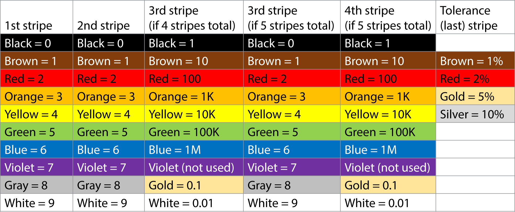
Resistors are rated in ohms (Ω) and reading the value of a resistor is easy if you can remember the rules, but I often use online calculators or the multimeter to confirm. Colored stripes on the resistor represent its value, and most resistors have three stripes indicating the value with a fourth the tolerance of the resistor. Some resistors have four stripes for the value and the fifth is the tolerance. On a four-stripe resistor, the first stripe represents the first value, the second stripe the second value and the third stripe is a multiplier. On a five-stripe resistor, the third stripe is a value and the fourth is the multiplier. There is a small gap between the last value and the tolerance stripe.
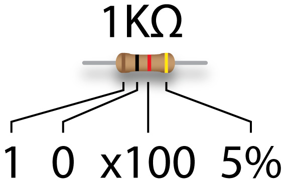
So, for a four-stripe resistor with brown, black, red and gold stripes, you can read that as a 1 KΩ resistor—1 and 0 times 100—with 5% tolerance, meaning the resistor could be as low as 950Ω or as high as 1.05KΩ.
It can be quite difficult to read a resistor—red, orange and yellow look similar—so you may need to use the multimeter to check these values. Fortunately, there are online calculators that will give you the colors for a given value or that will let you pick colors for each stripe and return the value for that combination.
2N3904 transistor
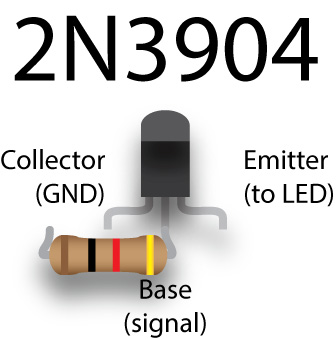
The ATtiny85 and ATMega328 microprocessors can only supply a small current to the output pins—not enough to light more than two LEDs. So, we need a way to connect a large number of LEDs to a larger power supply, using a signal from a pin on the microprocessor to activate a switch that makes that connection. Enter the 2N3904 transistor, a ridiculously cheap (50¢) component that acts as that switch. A signal sent from one of the microprocessor pins to the base leg of the transistor will connect other components like LEDs to a higher voltage. The signal voltage doesn’t need to be more than 0.6V, but we’re sending 5V, so there’s a 1KΩ resistor between the microprocessor and the base leg of the transistor.
Just to be clear: transistors don’t increase voltage or current. They simply provide components like LEDs access to a separate voltage or current.
The LEDs we want to light are connected to the emitter leg of the transistor, which is actually a path to ground via the collector leg of the transmitter. So, connect the emitter leg of the transistor to the cathode or ground leg of the LED, and the anode or positive leg of the LED to the higher voltage. In this case, however, we use a 5V signal from the microprocessor to the transistor, which switches the LEDs to the same 5V voltage that went into the microprocessor. But importantly, we’re not sending current through the microprocessor to those LEDs, we’re getting it directly from the AC/DC power supply adapter (wall wart).
IRF540N
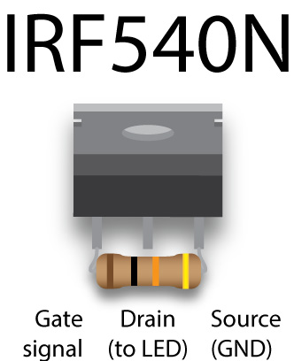
A MOSFET is another solid-state device, and for our purposes, we’re using it like a super-duper switching transistor. The pin layout of the IRF540N MOSFET we’re using is different from the 2N3904 transistor, but the idea is the same. We’re sending a 5V signal to the gate leg of the 540N, and the LEDs we’re driving (in our case, the LED strips in the two nacelles) are connected to the drain leg. The ground pin of the strips is connected to the 540N and the positive pin of the LED strip is connected to our 12V supply. There’s a pull-down 10KΩ resistor bridging the gate and source legs of the 540N which prevents accidental switching.
Capacitors
Capacitors store and release energy, sort of like a battery, although they can store and discharge quite quickly. Anyone who has inadvertently shorted a big capacitor in some sort of appliance like a television knows you can end up with a melted screwdriver and/or loss of consciousness. Fortunately, the value of the capacitors we’re using are unlikely to cause harm.
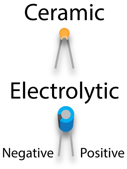
We use both ceramic and electrolytic capacitors in our board. Ceramic capacitors resemble little blobs of clay with two metal legs sticking out at a jaunty angle. The smaller value capacitors we use are ceramic, the larger ones are electrolytic. Unlike the ceramic, electrolytic capacitors are polarized—they have a positive and negative leg. Make sure the negative leg goes to ground. The negative leg is usually indicated by a dark stripe with white bars.
The value of a capacitor is rated in farads, however, a one farad capacitor would be a honking, big capacitor. Most of the electrolytic farads you’ll use for starship lighting are measured in microfarads. There’s a 10µF (microfarad/1/1000th of a farad) electrolytic capacitor we use to bridge the reset and ground pin on the Arduino Uno to keep it from accidentally resetting when using it as an in systems programmer. We use ceramic, 22 pF (picofarad/1 trillionth of a farad) capacitors between the legs of the ATMega32 clock crystal and ground. Electrolytic capacitors also have a voltage value, and for our board 16V would be fine. Larger values are also physically larger.
Electrolytic capacitors are generally clearly labeled with its capacitance and voltage, but ceramic capacitors requiring deciphering a code that I think is even more cryptic than resistors. Most ceramic capacitors generally have a two- or three-digit code. The first two digits are the capacitance in picofarads. The third digit is a multiplier and the value represents how many zeroes after the one. So a capacitor labeled with 104 is both 100,000 pF, 10 nF and 0.1uF. The 22 pF capacitors I used between the clock crystal and GND on the ATMega328 are just labeled 22, but they could also be labeled 220. Just like resistors, there are online calculators that help you decipher these codes.
Incidentally, the values of resistors and capacitors are quite odd because they’re spaced logarithmically. Online resistor calculators usually recommend the next highest common value.
ULN2803A
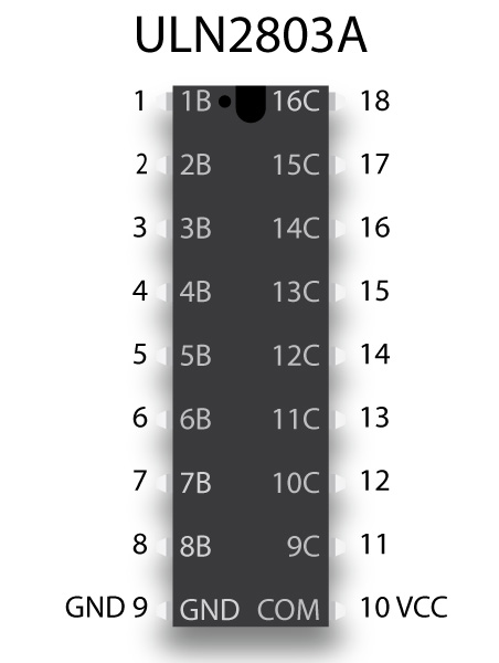
In an effort to further reduce the load on the microprocessor, we’re going to offload the lighting of the spotlights to the ULN2803A chip, a Darlington array. We can connect seven of the output pins of the ATMega328 to seven of the pins on the 2803 (the 2803 actually has eight input/output pins, but we only need seven). The 2803 can send up to 500 milliamps, but we need only a little of that.
The input pins are on the left side of the chip, the output pins on the right. (This chip is an anomaly because the layout of the pins makes sense.) Pin 9 (lower left) is connected to ground and pin 10 (lower right) is connected to our 5V power rail. Unfortunately, using the 2803A still ties up seven pins on the ATMega. Luckily, the next solution only uses up three pins while lighting eight sets of LEDs.
74HC595
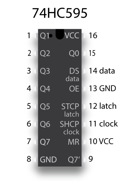
The 74HC595 chip is a shift register, it can convert a serial signal—of values from 0 to 255—coming in and turn it into up to eight separate 5V HIGH outputs. We only need three pins on the ATMega connecting to what are commonly called the data, latch and clock pins on the 595. The data pin receives the data that tells the 595 which of the output pins to light up.
That data is a little complicated because of what we’re trying to do. We want to simulate the effect of the reaction control system that are scattered about the ship. To fire the thrusters, we’re going to put the values that will light the thrusters into an array (more on that when we look at the actual sketch) and randomly retrieve one of these value at random times.
But in one of the most bass-ackward processes you can possibly imagine, we’re going to send a base 10 number and turn it into its equivalent 8-digit binary value. So, for instance, if we send the base-10 number 160 to the 74HC595, it will be turned into the equivalent binary number 10100000. Those eight digits equates to the eight output legs of the 595, and a one means send out 5V, and a zero means OV. So, two of the eight LEDs will light.
If we send the base-10 number 40 to the 595, then the equivalent binary number of 101000 will light another two RCS LEDs. You might notice that number is only six digits long, so the 595 will just add another two zeros at the beginning to give 00101000. In fact, all the values we’ll put in the array will only light two LEDs at a time, which is intentional. The 595 can only drive no more three LEDs at full intensity, although it can drive more lights at lesser intensity or for short durations. To play it safe, however, I’m limiting it to two “random” RCS burns at a time.
Notice that in addition to the number 8 ground pin and the number 16 incoming voltage pins, we will want to ground pin 13 and connect power to pin 10. Pin 13 is the output enable pin. If it went high (connected to power), the 595 would not light any LEDs. Pin 10 is the reset pin and if it goes low (connected to ground), the chip resets.
Setting the pins to go high involves three lines of code:
digitalWrite(LTCH_PIN, LOW);
shiftOut (DATA_PIN, CLK_PIN, MSBFIRST, 160);
digitalWrite(LTCH_PIN, HIGH);
The first line sets the latch pin low, which makes the chip ready to accept data. The next line sends data—in this case 160—to the data pin of the chip. In the actual sketch, instead of a value you’d see a variable. The third line sets the latch pin high, which actually sets the desired pins high.
When to use ULN2803A and 74HC595
There is a trade-off between the ULN2803A and 74HC595. The first chip can light up to eight LEDs at a time but requires using eight pins of the microprocessor. The second chip only uses three pins of the microprocessor but shouldn’t be used to run more than two or three LEDs before exceeding the maximum current output of the chip. The 2803 has the additional feature that it can power multiple LEDs per pin. The 595, on the other hand, has the feature that you can daisy chain additional 595s without requiring the use of more pins on the microprocessor, but each 595 still has the same current limitations.
LM7805
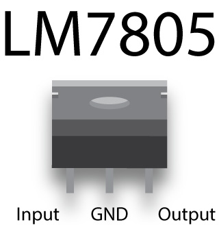
Our onboard power supply uses the LM7805 voltage regulator to step down the 12V input from the AC/DC adapter to the common 5V we supply all the components on the board. Just the like the IRF540N MOSFET, the 7805 has three legs, one attached to the 12V supply, one attached to ground and one that supplies 5V to the rest of the board. It’s not a very efficient regulator—the excess voltage is disposed of as heat, which is why it’s best to attach a heat sink to the back of the 7805—but it is simple. You could get by with just the 7805, but it’s best to attach some smoothing capacitors that bridge the legs of the 7805. We use a 100µF electrolytic capacitor across the input and middle ground pin, and a 10µF electrolytic capacitor across the output and ground pin. These capacitors ensure a stable 5V output.
JK16-050T resettable switch

This component, which resembles a ceramic capacitor, prevents the power supply from drawing more than 500mA current. It’s sort of a fuse, except that it can be triggered repeatedly (although that’s not a good thing). The switch isn’t polarized and is placed just after the 1N4001 diode between the 12V supply and the input pin of the 7805.
You’ll know it’s been triggered because the board has no power, and the switch is hot to the touch. Unfortunately, it’s not perfect protection because it’s not triggered instantaneously, and in that period some components might be damaged.
16Mhz clock crystal
This is not really a crucial component, but it does ensure the ATMega328 operates exactly at 16Mhz. If we had a lot of crucial timing in our sketch, it would be essential to attach a clock crystal to the ATMega, rather than depend on its internal crystal. If you look at an Arduino Uno, you’ll see such a crystal. Since the crystal doesn’t take up much space and is pretty cheap, it’s best to add the crystal across numbered pins 9 and 10. We also should add the 22pF ceramic capacitors mentioned earlier.
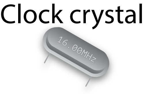
If you elect to use the ATMega328 without the crystal, you’ll need to install a different bootloader. Incidentally, we do depend on the internal clock of the ATtiny85, primarily because there is no option to use an external clock.
Buttons
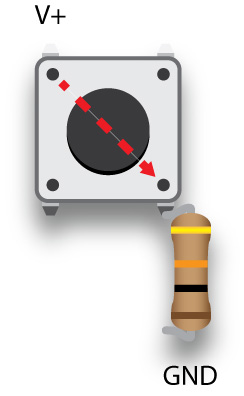
You’d think buttons were simple, but they actually are kind of complicated. We’re using momentary buttons to trigger the change from impulse to warp, and to fire weapons. These buttons only fire when the button is depressed, but we don’t want to trigger functions in the sketch repetitively while the button is depressed. We don’t want to rapidly go from impulse to warp and back again several times while holding down the button, for instance, so we need to set software flags to prevent this.
The most common momentary buttons have four legs and are meant to straddle the horizontal gap of a breadboard, although it doesn’t have to. If you look closely at the picture above, you’ll see that a positive voltage connected to the upper left pin will be transmitted to the pin in the lower left when the button is pressed. You should also notice a 10KΩ pull-down resistor that goes from that pin to ground. The resistor filters out electrical noise that might be interpreted by a microprocessor as a pressed button.
You should also know that even though there isn’t a connection from upper left to lower right until the switch is closed, there is always a connection from the upper left pin to the lower left, and the same holds true of the pins on the right side.
I actually bought two pin, “breadboard friendly” momentary buttons. The pins on most momentary buttons are actually a bit too wide to easily fit in the holes of a breadboard, but the buttons I bought fit perfectly.
Potentiometer
A potentiometer is a variable resistor that we use to control the 555 PWM LED dimmer. We could also have connected potentiometers to our microprocessors to fine tune the timing of the collision strobes or navigation lights, or the speed at which the deflect dish glows—except we don’t have any free pins for that purpose.
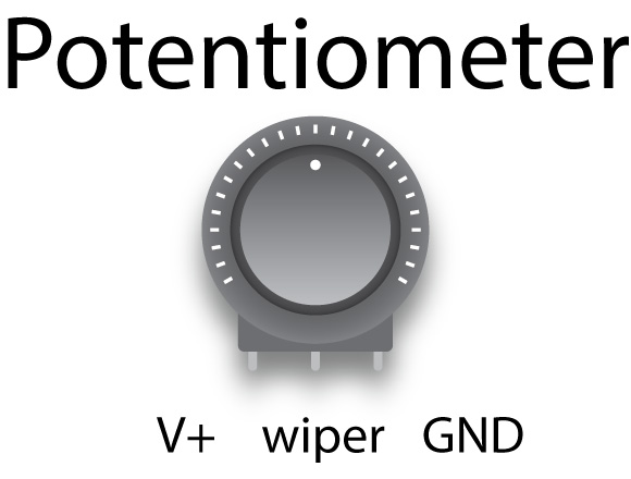
Potentiometers, or pots, have three pins and usually the middle pin is the wiper or the variable resistance value. The outside pins can be thought of as the input voltage and ground, but that’s not very clear in our 555 PWM board. It doesn’t really matter which outside pin you use for what, but it does change how the pot works, making the LEDs brighter as you turn clockwise, or dimmer as you turn clockwise.
The pot shown on the 555 PWM board is a rotary potentiometer, but I plan to use a slide potentiometer, reminiscent of the transporter controls on the original Star Trek show. I also plan to a use stereo slide potentiometer to adjust the volume of the speakers. This is essentially two potentiometers controlled by a single sliding knob.
A potentiometer used on a board is usually much smaller than the graphic above. Instead of a large dial, there’s usually a smaller dial fitted with a slot for the head of a screwdriver.