How to Light the Enterprise
This post begins a series of articles on how to light the Enterprise refit. This is a work in progress as I’m nowhere near completing my model, but I thought others might benefit from what I’ve learned so far. These article also supersede all previous articles on this subject.

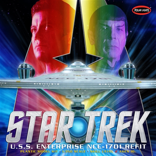
Although I am the author of this booklet, I do not claim a copyright. Anyone is free to copy, distribute and alter this booklet, although if you do alter it you should attribute yourself. Please feel free to use my drawings as you see fit. I recognize the copyright of any material I’ve use that I didn’t create, such as the movie screenshots that are the property of CBS/Paramount, and the box art of the model kit that is the property of Round2, and I beg apology of those companies.
Please feel free to download the PDF of this booklet, where you will find vector drawings of all the circuits and schematics.
June 2021
Introduction
I have been in love with the Enterprise since the original Star Trek show aired in the 1960s. The ship is an improbable melding of grace and power, implying an advanced technology is responsible for making such a delicate looking ship possible. When the Enterprise refit was introduced in the first Star Trek movie, I was even more in love. It is the epitome of “Starfleet clean,” ships so beautiful they seem ethereal—a far cry from the world weary, grungy look of Star Wars. Starfleet vessels are largely free of greeblies—details added to break up surface areas. Instead, the Enterprise refit was detailed through an intricate painting process that made it shimmer when seem from certain angles. There were both subtle variations and a larger, barely discernible pattern called “azteking,” that again implied a technology beyond our ken.
The refit was also bedight with a multitude of lighting effects, including collision strobes; navigation/formation lights; deflector dish and warp nacelle glows; RCS thrusters; and spotlights that shone on the ship’s registry markings. I’m a little embarrassed to admit—but not ashamed—that I tear up when I see the spacedock startup sequence in the first two movies, when the spotlights turn on in sequence to show the grand, gray lady waking up.

I’ve been trying to build the Polar Lights 1/350th scale USS Enterprise refit for more than a decade now.* It’s one of those very long-term projects that has languished principally because I’ve been unsure of how to light it. At first, I tried making a lighting circuit based on simple integrated circuits, like the 555 timer, but there was a limit to what my extremely limited knowledge of electronics could do. Then a friend gave me an Arduino Uno, essentially a computer on a single chip, that could, if I learned to program it, power the Enterprise.
Still, the project languished because although the programming wasn’t that difficult, it would still require a lot of circuitry to make it glow. Then I found a series of tutorials on the YouTube channel Ostrich Longneck that explained how to fire phasers, light the deflector dish and go to warp. But it wasn’t until 2020 and an excess of free time allowed me to design my own lighting circuit.
Starship lighting circuit
Eventually I ended up with a circuit based on two microprocessors, the ATtiny85 and ATMega328, plus a number of other integrated circuits, transistors, resistors and capacitors. I’ve managed to get just about every feature I wanted, including some I didn’t even know I wanted. These features include:
- Collision strobes
- Navigation/formation lights
- Deflector fade up/fade down
- Fade up/down blue warp nacelle glow
- Impulse engine fade up/down
- Photon torpedoes
- Phasers
- RCS thrusters
- Spotlights
- Sound effects
The lighting effects are mostly based on the first two Star Trek movies, The Motion Picture and Wrath of Khan. I’ve made certain decisions about these effects that don’t actually match every detail from these movies or subsequent movies featuring the refit or the Enterprise-A. For instance, I’ve decided:
- When at impulse, the main deflector and impulse deflection crystal glow amber. The magnatomic amplification crystal and the warp nacelles do not glow.
- When at warp, the main deflector and impulse deflection crystal glows blue. The magnatomic amplification crystal and the warp nacelles glow blue.
- When at impulse, the impulse engine glows red; it does not glow when at warp
- The RCS thrusters only fire when at impulse, not at warp
Some of these decisions are the result of my trying to observe the rules of how starships operate, even if the movies violate them, but frankly most of them, are the consequences of the limitations of my programming skills or the limitations of the chips that power the starship.
In that first category, I believe that the warp nacelles shouldn’t glow when at impulse, and you see that, for instance, during the Mutara Nebula battle in Wrath of Khan, when the Enterprise and Reliant are playing pin the tail on the starship. You’ll see the Enterprise passing over the Reliant, with the warp nacelles dark, because the ship is at impulse or perhaps even just using the RCS thrusters. But in other movies you’ll see the nacelles glow when at impulse. I can imagine reasons why the nacelles might glow when at impulse, but not as a general policy.
Of course, in the same nebula scene, you’ll notice that the impulse deflection crystal glows blue, when I think it should glow amber, reflecting the Enterprise is at impulse. But, of course, in the same battle, you’ll see the deflector glowing blue.
Here’s where my pedantic need to impose rules on what is just entertainment collides and colludes with the limitations of my skills and the limitations of my materials. We’ll go into this in detail later, but for now I’ll explain that two pins on the ATtiny chip are responsible for lighting the amber and blue LEDs to represent impulse and warp. The same impulse pin is responsible for lighting the LEDs for the deflector, crystal and impulse engine. The problem is that according to that famous spacedock startup sequence, the deflector glows while in spacedock but the impulse engine doesn’t glow until the ship leaves spacedock.
Unfortunately, there’s no way to accomplish this with the circuit as designed. Every pin on the on the ATtiny and ATMega is already assigned, so there’s no free pin to separately light the impulse engine. If I really wanted to, however, I could eliminate one of the two phaser pins of the ATMega—resulting in always lighting the same phaser emitter—and assign it to lighting the impulse engine. That’s unappealing because now the impulse lighting effect is handled by the ATtiny and ATMega, and it would be difficult to coordinate.
I could also do some ugly, low-level reprogramming to turn the reset pin of the ATtiny into a digital input/output pin, but if you make a mistake, you might end up with a bricked chip. Admittedly, the chip is pretty cheap and there are ways to fix the chip, but I don’t think most people would want to attempt this. This is one of those cases where I’m content to have the impulse engine start while in spacedock.
Should you do this?
Before you decide to build your own starship lighting circuit, I should mention there are several companies that sell pre-made circuits that will do just about everything you might desire. Although these circuits aren’t inexpensive—you might spend $250—the cost of buying all the components you need to build your own add up. This includes a supply of assorted resistors and capacitors, wiring, breadboards, perfboards, soldering iron, wire strippers and assorted tools like multimeters, tweezers, pliers and flush cutters. You could easily spend several times over that $250.
Of course, if you already have a lot of this equipment and components, then the cost shifts in your favor. For instance, you’ll only need one 16Mhz clock crystal for this project, but I bought a package of 20 for $7. I have enough components to light three starships. I was also able to add specific features that I wanted, so my lighting board is unique.
I will warn you that you’re in store for a lot of frustration, interspersed with occasional cries of success. Several times you’ll be tempted to give up, but I hope this guide will help. I would be delighted if your design differs from and exceeds mine. In the next chapter, you’ll find out what you’ll need to know if you attempt this.
Development Work Flow
My development work flow should be different, but still similar to yours. Hopefully I’ve done most of the ugly stuff for you, but you still might have to do some grunt work if you decided to add different features to your board.
I started by writing sketches for the Arduino Uno connected to a breadboard. I wrote the ATtiny sketch first (strobes, nav lights and deflector) because it’s relatively simple. It worked perfectly the first time, but then I had to upload the sketch to the ATtiny and nothing worked. After a day of scratching my head, I realized that I had forgot to change the Uno (or ATMega) pin assignments to the corresponding ATtiny assignments.
Then I wrote the spotlights, weapons, RCS thrusters and sound sketch that would go on the ATMega. Testing it on the Uno was a slow process as I discovered the mistakes I’d made, but it was steady progress. Uploading the sketch to the ATMega, however, was very painful because I’d forgotten the process that you’ll find in the chapter Programming the Microprocessor. Even after I successfully uploaded the sketch, however, I still had problems getting all the components working. Getting the Adafruit FX Sound Board working was especially problematic until I told the board to reset in the setup block.
Finally, I had both sketches working and uploaded to the appropriate microprocessors. The next step was getting both microprocessors and the other ICs and components on a single breadboard, with the onboard power supply. You can read about these problems in the More About … chapter.
Of course that wasn’t the final, final step. I had to transfer everything to the solderable perfboard and of course I made mistakes. I’m sure you will make mistakes, which is why you’ll need the de-soldering tools mentioned in the What You’ll Need chapter.
If you decide not to add any features or make any changes to the sketches, you might be able to skip the testing on the Uno and proceed to uploading the sketches to the microprocessors. (You’ll still want to test compile the sketches in the Arduino IDE.) But debugging sketches on the microprocessors is difficult, so if there are any problems, you’ll probably want to test using the Uno.
I realize this is daunting, but hey, this is easy compared to painting the Enterprise.
NEXT: What You’ll Need to Know
*Actually my efforts at lighting an Enterprise go back to the AMT 1/537th scale kit and Paul M. Newitt’s Starfleet Assembly Manuals
