
What You’ll Need
At a minimum, you’ll need these tools:
- Breadboards, on which you’ll test circuits
- Jumper wires to connect the components on the breadboard
- Solderable perfboards, on which you’ll mount your finished circuits
- Wiring: I bought an assortment of 26- and 30-gauge wiring in six colors
- Soldering iron and solder
- Wire strippers capable of stripping the wiring mentioned above
- Tweezer and pliers
You might also want:
- Chip removal and insertion tools: it’s very easy to bend the legs of ICs as you insert or remove them from a breadboard. These tools are cheap and very handy.
- Multimeter: I use mine primarily to check continuity, voltage and resistor values—occasionally for amperage
- Third hand tool and/or vise for holding wiring and components while soldering
- Crimping tool for making Dupont and JST connectors
- I have a dedicated modeling desk with several work lights to see what I’m doing
- Resistors and capacitors are best bought as assortments, with individual purchases required if you lack specific values
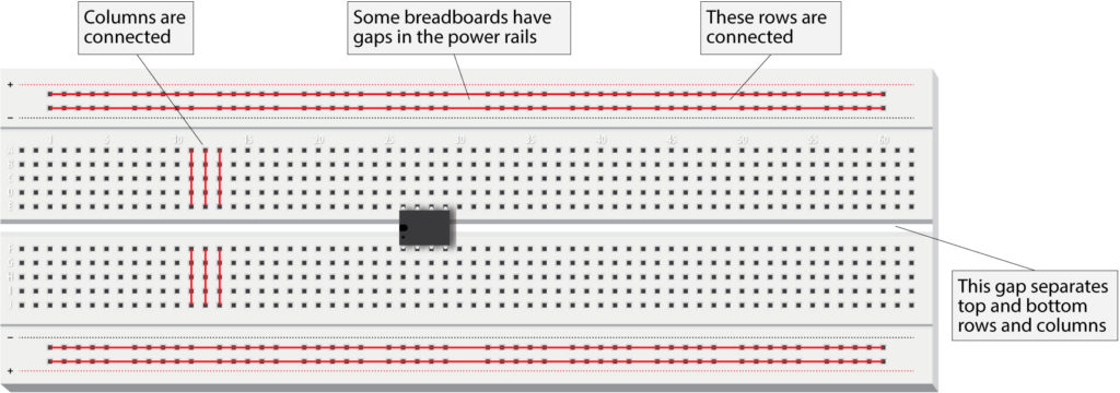
Breadboard
You use breadboards to build and test your circuits. You can plug components into the breadboard without soldering and connect them with jumper wires that again simply plug into the holes of the breadboard. In the full-size breadboard shown above, you can see that the columns are connected, so each hole in a column has an electrical connection to the hole below. The holes are spaced 0.1” (2.54 mm) apart, which more or less corresponds to most components, such as the spacing of the legs of an IC.
The top and bottom rows are connected and are used as power rails, so a positive voltage or ground connected to any hole in the row is available to all the holes. In some breadboards, however, there’s a break in the middle, which allows you to have a different voltage like 3.3V on the left and 5V on the right. Jumper wires can bridge the break to make a continuous voltage. There’s another break in the middle of the board that separates the columns in the top half from those in the bottom, and also breaks the power rails at the top from those at the bottom. Often a jumper is used to connect the power rails top and bottom.
Integrated circuits—or chips—are inserted into the breadboard horizontally, straddling the gap through the middle. Jumpers plugged into the holes above and below the chip then connect directly to the pins of the chip.
Breadboards are used for prototyping—seeing if the thing works—and are not intended for long term use. Just plugging a wire into a hole is a tenuous connection and jumper wires often break free, confounding you if you didn’t notice.
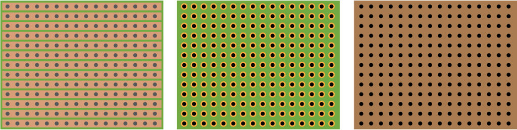
Solderable prototyping or perfboard
For permanent use, you will want to solder components onto a solderable perfboard (also called a solderable prototyping board). A perfboard has the same spacing as a breadboard, and there’s a lot of different layouts. In the picture above, the first example shows connected rows. The second example has individual pads and the last has holes but no solderable pads.
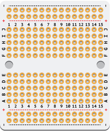
I really like the Adafruit Perma-Proto Breadboard PCB, which comes in quarter-, half- and full-width sizes. These boards are clearly labeled and have the same layout as a breadboard, making it easy to transfer a circuit designed on a breadboard.
Soldering iron
Get a decent soldering iron with a temperature selector. I have a Hakko FX888D that costs about $100, but you could find a good Weller variable temperature soldering station for under $40. A soldering station usually includes a holder and a sponge for tip cleaning. The Hakko has an additional coiled brass tip cleaner. I can precisely set the Hakko for 500° F, which adequately melts the solder but doesn’t destroy the tip.
By the way, solder is usually composed of lead, tin and rosin. You’ll want good ventilation to remove the rosin fumes and you should wash your hands after handling solder.
You’ll probably also want a solder remover tool and/or de-soldering wick, for when you make a mistake and need to remove a component.
Another good investment is a third-hand tool and/or vise, but most modelers already have these. And finally, locking tweezers or heat-sink clamps would be useful to prevent overheating components, but again, most modelers probably have these.
DuPont/JST crimper
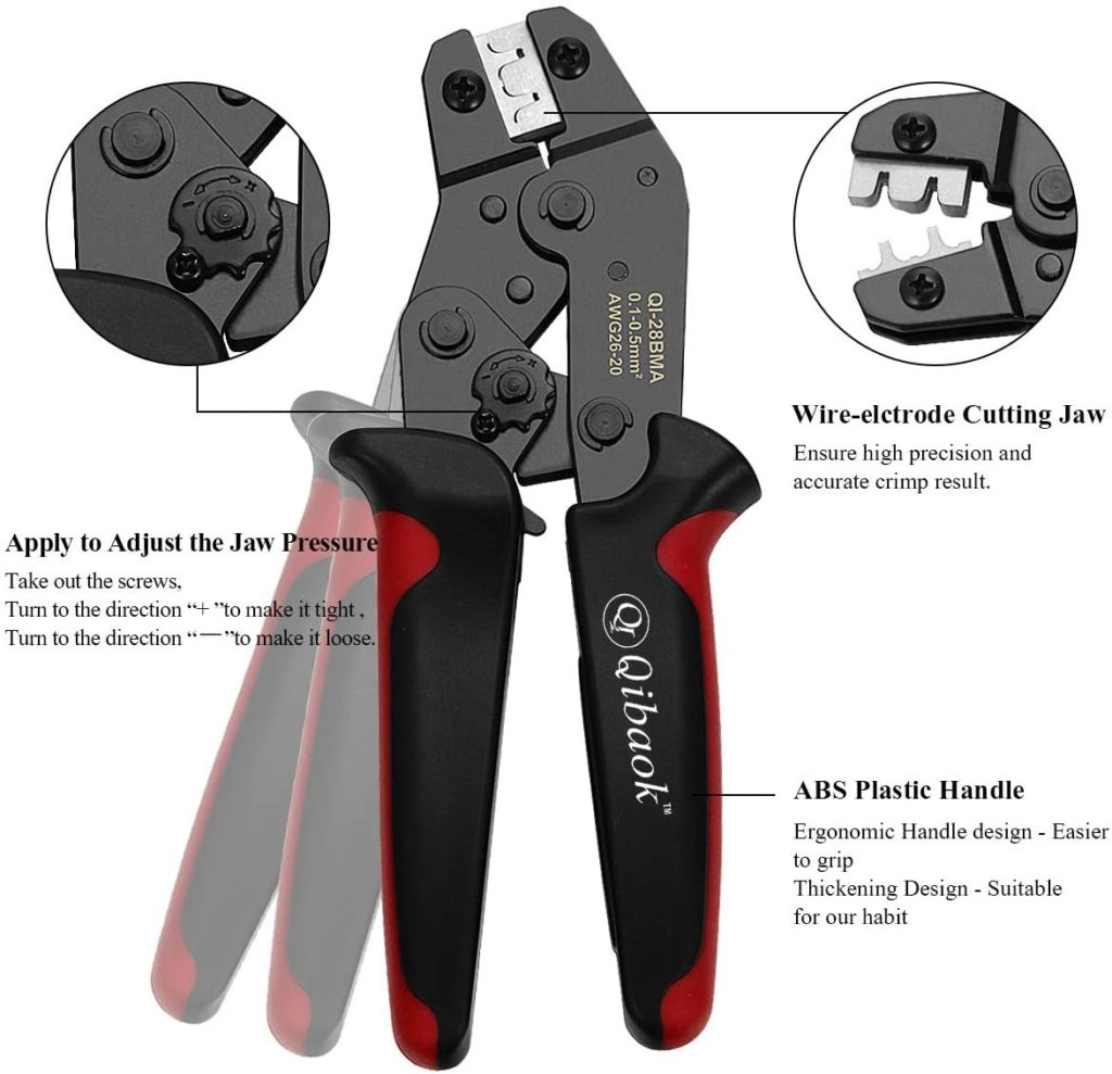
You can solder wires directly to the perfboard, but there are many places where it would be nice to have a connector that can be easily attached/removed. I’ve bought a crimping tool to make DuPont header pins and JST-XH connectors. Connectors are not a must have, but I prefer neat and tidy wiring and hope to avoid the nightmare of shoving wire spaghetti into the saucer section.
DuPont connectors are dark, gray plastic blocks into which metal, female connectors are inserted. The connectors have metal jaws that are crimped around wire leads, using the tool mentioned. The connectors are then slipped over metal, male header pins that are soldered to the perfboard. DuPont connectors come in single, double, triple, etc. widths and then can be glued together to make double rows. Header pins are usually sold in long rows and can be snapped apart to make the necessary length.
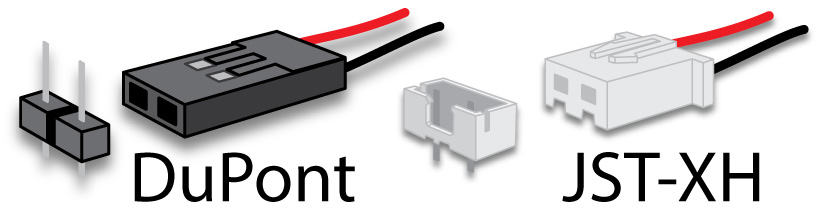
DuPont connectors are not positive locking and are just held in place by friction, although an 8-pin connector placed over an 8-pin header is usually pretty tight. JST-XH connectors differ by having locking tabs, although they are otherwise similar to Dupont connectors. They’re usually molded in white plastic and again a metal, female connector is crimped onto wire leads and then inserted into the housing. The connector is then slipped onto the male pins that are soldered to the perfboard. Unlike DuPont connectors, however, you cannot gang them (place them immediately adjacent without a gap) or glue them together.
Concerning crimping tools, as with most things, you get what you pay for. A high-quality tool will probably cost $100, whereas the tool I bought was $40, which included an assortment of DuPont and JST connectors plus a three-foot length of ribbon cable. Expect to mangle a number of crimps before you get the knack of the tool.
Arduino
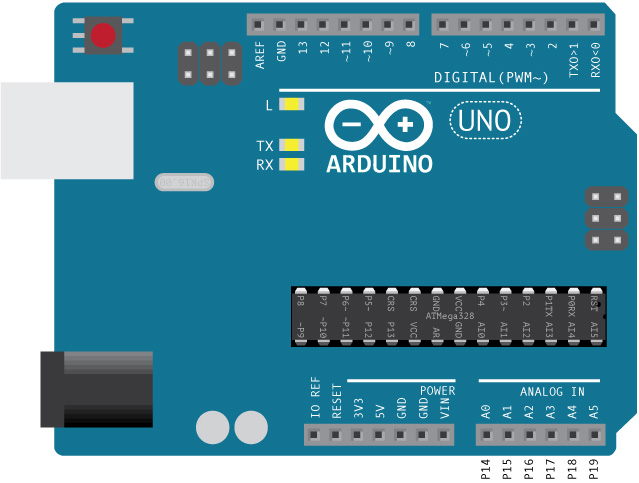
You will need some flavor of an Arduino, and I’d recommend getting an Arduino Uno because it uses the same chip you will use on the starship lighting circuit. It comes with header pins (actually the female half) that make it easy to run a jumper wire from the Uno to a breadboard. You could probably buy a cheaper Arduino clone, but at $23, I think you’ll be better off getting a genuine Arduino. You could probably also get an Arduino Nano, but you’ll need to plug it into a breadboard or use a shield to make easy connections, at which point you’ll basically have an Arduino Uno.
Incidentally, there is an Arduino Mega 2560 that has a lot more input/output pins than the Uno. You probably don’t want to use this because it uses a different processor than the ATMega328. I mean you could, but you’d have to keep changing the pin numbers when testing on the Arduino Mega 2560 and when uploading to the ATMega328. You might also be tempted to use those extra pins, only to find out they’re not available on the ATMega328. Also, I think the ATMega 2560 chip is only available in a surface mount design, making it nearly impossible to use with a perfboard.
Bench power supply
You may wonder why you need a bench power supply, considering that we’re making a 5V supply right on the main board. But it’s very nice to have a variable supply with a lot of amps to test your circuits without having to create a power supply from scratch each time.
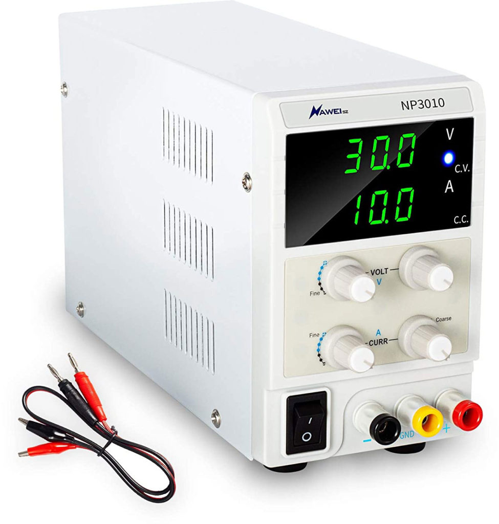
A bench power supply is a luxury item to be sure, but it certainly comes in handy if you make a lot of circuits. You can buy a bench power supply for $50–75. Another popular option is to cannibalize an old ATX power supply, which will have steady 3.3, 5 and 12V output. Just trim away the wires you don’t need. You’ll need to add some plugs and a case, but it’s very simple. Or, you can create a variable supply using an LM317 voltage regulator and a digital readout that shows voltage and amperage. The latter is extremely useful in determining what size power adapter you’ll need for the finished model. If you see that your circuit is drawing 1.4 amps, then you’ll know you need a 2 amp power supply. Note: Give yourself room on power supplies. Using a 1.5 amp supply would probably run hot.
Multimeter
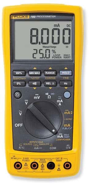
Of course, if you have a multimeter, that will also show you how many amps your circuit is drawing. You don’t need a very fancy multimeter for this project. You’ll mostly be checking continuity—whether there’s a solid connection between components. I occasionally use a multimeter to double-check the value of a resistor if I’m too lazy to look it up. And as mentioned, I also use it to determine the current draw of a circuit.
In the next chapter, we’ll take a closer look at the components you’ll be using in the final circuit.
NEXT: Lights and sound